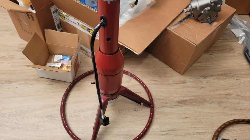
Since the weather hasn’t been conducive to working outside, I chose to work on wiring the new Ididit steering column. I could tackle that job inside where it is warm and dry. The column comes with a turn signal switch that terminates in wires with preinstalled crimp on pins. It also comes with a connector that will attach to the under-dash connector for my car’s wiring harness. It appeared that this would be as simple as pushing the pins on the wire ends into the correct locations on the supplied connector.
My first step was to make sure I could identify all of the wires. I used the wiring diagram in my shop manual and compared it to the documentation that came with the steering column. I was surprised to find that all the color codes on the new steering column matched up with the color codes on my under-dash wiring harness. Here are the wiring diagrams from the shop manual as well as the instructions from the Ididit steering column. Both diagrams include my notes as to the color coding.
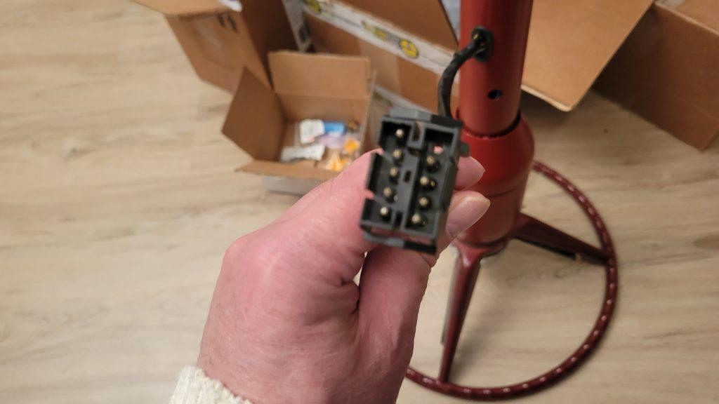
Armed with this knowledge, I turned to inserting the wire pins into their correct locations on the connector. I immediately learned that the pins didn’t fit. I puzzled over this for a few minutes before I realized that the new turn signal switch wiring used female pins, but the connector required male pins. The kit did come with a full set of both male and female pins, as well as both male and female connectors. I decided my best course of action was to cut off the female pins on the turn signal switch and replace them with the correct male pins. In the past when installing these types of pins, used a pair of needle nose pliers to bend and crimp the pins and then I had soldered the pins on. This always worked, but the results never looked anywhere as nice as when the factory crimped the pins on.
I contacted a friend who could advise me on the best way to achieve the correct looking factory crimp. I learned that there are special (and expensive) tools required for this. He recommended that I crimp the pins and then solder them on like I have done in the past. While not as good as crimping with the tool, it should work well enough. So that is the approach I took. I cut off the female pins and then carefully crimped and soldered on the male pins. Then using the wiring diagrams, I inserted the pins into the correct locations on the connector. Then I wrapped the wires in electrical tape to make the harness look nice and tidy. For not having the correct tool I feel like it came out fairly well.