
It’s been two months since I ordered my EPAS conversion kit. The vendor says they are waiting for the tilt column I ordered with the kit. They told me that they expect to receive more tilt columns in January and should be able to ship my order after that. My current expectation is that I won’t receive anything until February at the soonest. With that delay in mind, I decided to switch gears and find another automotive project to occupy some of my time. One thing that has been bothering me for quite some time is a squeak in the driver’s side front suspension. I’ve been pretty sure that the squeak comes from the upper control arm inner shaft. So sure, in fact, that I had already ordered a set of replacement upper control arms from OpenTracker Racing about two years ago. I decided it was time to install them.
Since I was replacing the upper control arms, it made sense to do a modification to the control arm mounting point that should improve handling. The objective was to lower the control arm mounting point by one inch by drilling new mounting holes in the shock tower. This modification was developed by a Ford engineer, Klaus Arning, and was done to the early Shelby Mustangs. It improves handling by lowering the center of gravity and also providing a better camber curve as the suspension travels. The modification is proven and well documented, with many write-ups and references to this modification on the Internet. Here is a link to one article on the DazeCars web site. Similar to my already having new upper control arms in stock, I also had the template and 17/32″ drill bit I needed to make the modification stored in the same box with the control arms. At this point in time, I felt that that I was ready to proceed with the modification.
The first thing I did was take a look to ensure I could reach all the fasteners I need to remove and replace. The upper control arm bolts go through the shock tower into the engine compartment. You have to remember that this Mustang is a big block car, so engine compartment clearances are all extremely tight. It appeared that there was just enough room on the passenger side to remove the control arm. The driver’s side looked very tight, but I thought it was doable. I was correct, but just barely correct. I’m certain a small block equipped car would be much less challenging. It might have almost been easier to remove or at least raise the engine for clearance.
I chose to begin with the driver’s side since I was certain it would be the more difficult than the passenger side. I removed the shock absorber and inserted my spring compressor. I tightened up the compressor just enough to hold it in place as I removed the upper control arm bolts. It was quite a struggle to remove the bolts that go through the shock tower into the engine compartment. I was not able to actually touch the nuts with my hand, but after a lot of trial and error and juggling of tools I got it unbolted. For the upper ball joint, I got to use the ball joint removal tool I had built. I posted about building that tool here. I loosened the bolt for the ball joint, inserted my tool, and put some pressure on the ball joint stud. A sharp hit with a hammer on the spindle caused the ball joint to pop right out. At that point I was able to remove the upper control arm and coil spring.
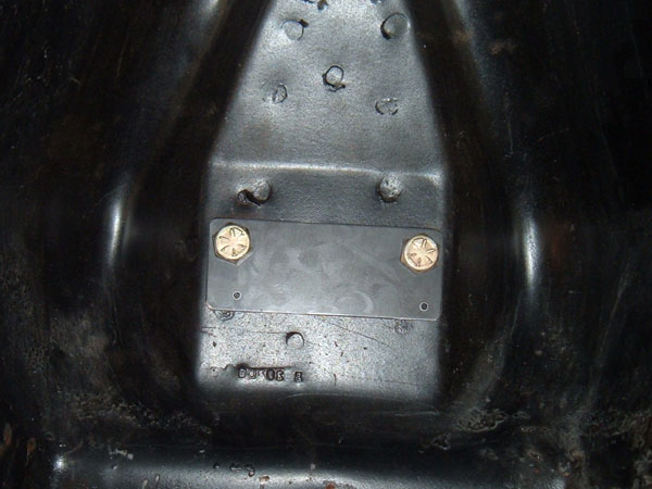
Next I began preparations for the Arning drop modification. The first step was to install a metal template I had purchased to guide me in drilling the holes. I usually manage to mess up my measurements when drilling so I was glad to have a template. I had a really difficult time bolting the template into place due to limited clearance between the engine and the shock tower. I ended up using an extending magnet retriever to hold the nut and washer in place while I inserted the bolts and screwed them down. Here is a picture I borrowed off the Internet of a template bolted in place.
I started trying to drill the holes using some brand new titanium coated drill bits I had purchased at Harbor Freight. After trying these bits, as well as bits from several other drill bit sets I had on hand, lubricant, and about an hour solid with little to no progress I decided to take a break for the day, research, regroup, and try some more tomorrow.
After some research on the Vintage Mustang Forum I learned a few things that I believe helped. First was to not run the drill at maximum speed. Apparently it cuts metal better at a reduced speed. I had been using the maximum speed of my drill because I thought that would make it cut faster. I also purchased a set of cobalt drill bits at the local hardware store. I don’t think this was absolutely necessary, but I wanted every advantage I could get. I ended up only using the 1/8″ cobalt bit to get the hole started. After that my other bits worked fine. Another recommendation was to use a step drill bit. I already had one, and I did find that it cut pretty well after the hole was started with the cobalt bit. The issue I had was that the shock tower metal was thicker than the steps on the bit. This meant that the next larger size hole would start cutting before the prior size had completed. Once I got to the size I wanted, I needed to finish up the hole with a regular drill bit to prevent starting the next size hole.
Armed with all this information I gave it another try. This time I was able to drill the two 1/8″ pilot holes using the cobalt bit, plenty of lubricant, and a medium speed on the drill. After the pilot holes were drilled, I removed the template. After some time and effort were applied, I was able to use the step drill and my standard drill bits to get the holes to 1/2″. From my reading the hole needed to be 17/32″, but a number of people said that they were able to get it to work with a 1/2″ hole. Knowing this, I test fitted the new upper control arm to see if I needed to enlarge the hole to 17/32″. The control arm studs would start in the holes, but I felt the fit was too tight and could damage the threads on the control arm studs. I grabbed my 17/32″ drill bit and went to put in my drill chuck. Unfortunately for me the bit had a 1/2″ shank and my drill had a 3/8″ chuck. I searched all the drills I had on hand, but none had a 1/2″ chuck. That meant another trip to the hardware store to purchase a drill with a 1/2″ chuck. I decided to let that wait until the next day and went to lunch with my wife instead.
The next morning I went to the local hardware store and purchased a drill with a 1/2″ chuck. Once I got back home, I went back to work finishing drilling the holes. I finished in no time and upon test fitting, the control arm fit with no issues. Now just one more difficult part to complete, getting the washers and nuts on the control arm studs and tightening them down. This was challenging and required some creativity. A small block car would probably not be nearly as challenging due to the additional clearance between the engine and the shock tower. Using a combination of my extending magnetic parts retriever to hold the nut and washer, a 3/4″ offset open end wrench, swivel ratchet, and a lot of sweating and swearing I managed to get the control arms bolted back in using the new holes I had drilled. I hope I never have to replace that control arm again and that the passenger side is not as difficult to replace.
Once I had the control arm securely fastened, I proceeded to install the coil spring and shock. Then I replaced the wheel and tire and lowered the car to the ground. I bounced that side of the car up and down a bunch of times and there was no more squeaking. I didn’t measure the car’s height before doing the drop and I can’t really notice a difference between the side I dropped and the other side which I haven’t dropped yet.
Unfortunately, a combination of weather, driveway repair, COVID, and surgery will delay my replacing the control arm and doing the drop on the other side of the car. But I feel good knowing I have already completed the more difficult side of the car. I’ll post back when I complete the other side, but it might be a few weeks before I can work on it again.