Author Archives: sdcohe

Dash Plaque Display Board

I’ve collected a number of dash plaques and was wondering what to do with them all. I did some quick research online and found that people either put them on their dash, threw them out, gave them away, stored them in a shoe box, or made some kind of display for them. I decided to mount them so that I could either show them with my car or hang them on the wall.

First I went to Target and purchased a poster frame. The one i bought was 18″ x 24″ and was less than $10. I probably should have picked a larger one but I didn’t want to invest a lot of money in case it didn’t work out. I also purchased some Scotch permanent mounting squares to mount the plaques to the frame. Several of the plaques already had double sided sticky tape on them but I used the mounting squares so the plaques would all be the same distance off of the board when mounted. In afterthought it may have looked interesting if the mounting depths had varied.

This is the poster frame I bought.

Poster Frame from Target

These are the mounting squares I bought.

Scotch Permanent Mounting Squares

The next step, arranging the plaques on the poster frame, was the most time consuming (at least for me). Before I mounted the plaques permanently, I laid them out on the frame so I could move them around and arranged them how I wanted. This took me quite a while before I found an arrangement that made me happy and was pleasing to the eye (at least in my opinion).

I started out arranging the plaques in chronological order. This left a lot of empty spaces. I moved the plaques around to make them fit better but still keeping the years together. This let me fit more of the plaques on the board, but there was still wasted space and leftover plaques. I decided to try arranging the plaques by car show. This let me fit most of my plaques on the board, but it looked unbalanced to me as all the large plaques were grouped together and all the smaller plaques were also grouped together.

The final arrangement I ended up with was to place the plaques randomly, trying to keep the years somewhat together and to not place plaques from the same show next to each other. This made for a more balanced looking arrangement and gave me the flexibility I needed to fit most of my plaques on one frame. I used the mounting squares to attach the plaques in the arrangement i had laid out. I had two very large plaques left over, so I saved them for my next frame after I collect more plaques.

This the arrangement I ended up with.
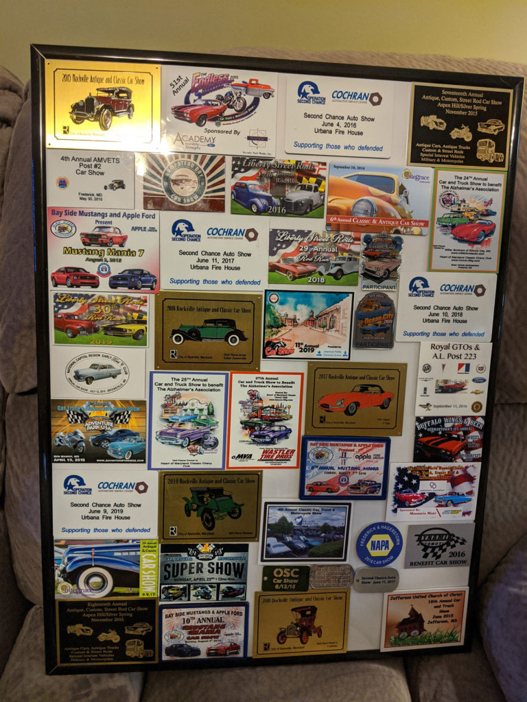
Picture of mounted dash plaques
Dash Plaques

Winter Projects 2019-2020

The car was reliable all season, even making the trip to Ocean City, MD and back. While we were there it was our only means of transportation. It got me back and forth to several other shows, and did a small parking lot “acceleration demo” for another car enthusiast. With that said, my only real complaints are a small squeak in the front suspension, the front bumper isn’t perfectly aligned, and there is a tiny dent on the right hand side front fender from some PVC tubing that fell over in my garage. None of these “issues” are very high priority, and I could probably get by without doing any winter projects beyond normal maintenance.

My ideas for potential winter projects are:

  • Rebuild front suspension. This isn’t really necessary as everything is tight and the alignment is still good. Seems like overkill to fix a small squeak. However it would give me the opportunity to add some upgrades if I choose to, such as solid strut rods, roller bearing idler arm, roller bearing lower control arms, and possibly a Monte Carlo bar.
  • Remove and align the front bumper. Most people don’t even notice the small misalignment of the bumper, but it still bothers me. A fair bit of work for a small reward. But I probably will still fix it.
  • Paint less dent repair for the passenger side fender. I would have to hire somebody to do this for me.
  • Polish/buff the exterior paint. I may attempt to do this myself as I have the equipment. But I may choose to hire a professional if I’m not satisfied with the results of my attempt. If I hire a professional detailer I will have them do the interior and exterior, as well as the engine compartment.
  • Replace the exhaust tips with larger diameter ones. The current exhaust necks down from 2.25 inches to 1.875 inches just before the exhaust tips. I could modify the existing exhaust to keep a consistent 2.25 inch diameter all the way to the exhaust tips.

I’m not certain how much of this list I will tackle this winter. I don’t need to do any of these items. It all depends on my motivation and more importantly on my health.

Minor Maintenance

I usually refrain from making repairs during the driving/show season, but there were a few nagging issues that were bugging me. I felt that the repairs would be minor so I didn’t believe that I was risking disabling the car and missing out on driving time. There were 3 issues I wanted to address.

Issue 1: The clutch pedal was not returning all the way after depressing it. I noticed this during the Spring 2019 boardwalk parade in Ocean City. If I nudged the pedal from behind it would come the rest of the way back up. I wasn’t sure this would be an easy fix, so I did some research into roller bearing conversions for the clutch support. This conversion goes beyond what I would do during the driving season, so I would be required to make the repair as a part of my Winter maintenance. But before I plunged into the deep end I decided to try some white lithium grease on the under dash linkage. I stuck my head under the dash and gave a few sprays onto the linkage. That freed everything right up and the clutch pedal works fine now. Issue #1 handled.

Issue #2: The engine ran well but seemed to be using more oil than I would like. After a while the idle got a bit rougher as well and I could see some smoke under hard acceleration. I wondered if the engine might be sucking in oil through the PCV valve. I pulled the PCV valve and checked it in the only way I knew. I shook it to make sure it rattled, which it did. Then I looked into the grommet in the valve cover to see the condition of the baffle that prevents the PCV from sucking in oil. There was no baffle in my valve cover. I did some quick research and found a replacement grommet that is supposed to prevent oil from entering the PCV valve. I ordered the grommet and installed it. My other option was to replace the valve covers with a pair that has a baffle. This is the proper long term fix. But in the short term the new grommet appears to be helping. I need to keep track of my oil levels and make sure that was the problem. Hopefully Issue #2 is addressed, even if it is only temporary.

Issue #3: The belt line weather stripping on both doors was lifting at the ends. There are supposed to be screws at the ends holding then down, but my replacement weatherstrip didn’t have screw holes so I never installed the screws. I got out my drill, made the holes, and installed the screws. Issue #3 fixed.

Hopefully that handles the minor issues until this winter. Now back to driving and car shows.

Ride of the Month

I joined the Vintage Mustang Forums in 01/2014 to help me find information about repairing my Mustang. This forum turned out to be a wealth of information as it had many extremely experienced members who have restored and repaired many cars. I was mostly a lurker, using the site as a great resource. Occasionally I would make a post if I felt I had something useful to contribute.

On 3/22/2019 I was contacted by one of the moderators who wanted to know if I would like to have my car chosen as the ride of the month. Would I? You better believe I would!

I had to spend some time writing up the story of my car and attaching pictures. This wasn’t easy as I had 45 years of information to cover in only a few paragraphs. Still, I was able to put together a document, with pictures, to be posted on the forum. After the story is posted I’ll add a link to it in this posting.

Update: I was contacted by a site administrator for the VMF. He said my car was selected as the May 2019 ride of the month. I’ll post a link sometime in May after the VMF site is updated.

Update #2: Here is a link to the posting. https://forums.vintage-mustang.com/ride-month-winners/1156796-congratulations-sdcohe.html

DIY Throttle Linkage

One small nagging issue I had was that the replacement Holley carburetor I was using didn’t have the same attachment point for the throttle linkage. This prevented me from using the original clip that Ford used to attach the throttle linkage to the carburetor. I had managed to come up with something using a spring clip that was holding together fairly well. I had used this same solution in the past, and it eventually came loose after quite a bit of driving. I always had this fear in the back of my mind that this clip would come off just like the old one had. I knew that I couldn’t be the first person to run into this throttle linkage attachment problem. So I did some research on the Internet.

I learned that I definitely wasn’t the first person to have this issue. I also found a very clever DIY solution that looked nice, was easy to build, and used common and inexpensive parts. This is the link to the article I found. https://www.fordmuscle.com/archives/2004/08/ThrottleLinkage/index.php

I took some measurements, looked at online parts catalogs from my local hardware stores, and placed an order for the required parts. Once the parts arrived, I made some more measurements and did some cutting with a hacksaw. I also purchased a new throttle return spring and bracket since the spring I was using was the original 50 year old part. I had to do some bending to get the throttle return spring bracket to clear the new throttle linkage.

I feel that this DIY solution works well and has a professional look to it. I haven’t had much of an opportunity to drive the car with the new linkage. The only thing I can say at this point in time is that the new return spring is lighter than the original and I tend to step on the throttle harder than I need to. Hopefully I can avoid getting any speeding tickets until I adjust to the more sensitive throttle.

Fuel Gauge Calibration (return)

We had another nice weather day and it was time to get back to work on the MeterMatch installation. I disconnected the battery and pulled out the instrument cluster. I’ve done it so many times now that it doesn’t take me very long to remove it. I did notice that some of my previous wiring efforts could use some organizing. I decided to address that while i was building and installing my wiring harness for the MeterMatch. Unfortunately I didn’t give any thought to taking pictures and visually documenting my progress. Sorry about that.

I chose to start by installing the harness I had already built onto the instrument cluster. Since I had used my spare cluster to build the harness this step was easy. Everything plugged in as it should, and I used wire ties to attach the new harness to the original cluster harness. I also dressed up the tachometer wiring harness I built a few years back by using wire ties to attach it to the cluster harness as well. That looked a whole lot neater.

Next I measured wires to go from the console to the instrument cluster. Using those measurements I built a wiring harness to go from the instrument cluster fuel gauge to the MeterMatch which I planned to install in the console. I used connectors I got from a trailer supply house as they matched some of the factory connectors. Then I routed the harness and used wire ties to attach it to the existing behind dash wiring harness. I also cleaned up more of the tachometer wiring I had previously added.

The last harness to build was the wiring for power to the MeterMatch. I also installed a glass fuse holder and a 2 amp fuse for protection. I got the 12 volts required from the accessory port of the ignition switch. I used an existing screw behind the dash as a ground.

At this point I was ready for a quick test to make sure I had wired everything correctly. I connected the instrument cluster back up and turned the key to accessory. I had already determined that the tank should be about 3/4 full. Prior to installing the MeterMatch the gauge read closer to 3/8 full. I turned the ignition key to the accessory position and the fuel gauge slowly moved up to indicate 3/4 tank. I tested out everything else in the cluster and it all appears to be working properly. I still need to test the speedometer before I button everything back up.

My plan is to test drive the car and then fill the tank up after the drive. That will let me see how much gas it takes to fill the car compared to what the gauge read just prior to filling up. Then I can adjust the full setting on the MeterMatch if required. Further calibration will need to take place “on the fly” as I drove and fill the tank over the next show season. I’ll make another post after I have burned up a few tanks of gas and made any calibration adjustments.

Driver’s Window Regulator

It took a week before I had another warm day and was able to get back to work on the driver’s door innards. Having to wait was getting on my nerves as I hate to leave work partially completed. I have to admit I did find some opportunities to test opening, closing, and locking the door. But this was just playing around, not getting real work accomplished.

After watching several online videos I felt that it would make reassembly easier if I removed the guide located at the bottom of the window. I was able to get the regulator out without removing this guide, but reinserting the rollers for the regulator back into the guide looked like it would be tricky. With the guide removed I could insert the rollers outside of the door and then insert the regulator and guide as one assembly. This turned out to be a great plan, but with one hitch.

There are three screws that hold the window guide to the window. Two came out fairly easily. The last one didn’t want to budge. I had a screwdriver that fit tightly into the screws I removed, but the head on the last screw was starting to get dug out. It looked like I would have to drill the screw out and replace the clip that it screwed into in the back of the window. That’s when I saw that only two screws used clips and the third screwed into a threaded hole. Of course that was the screw that wouldn’t come out.

There were several ways I could proceed at this point. I could drill off the head and try to unscrew the rest of the screw from the back of the window. I checked and it was accessible. I could remove the window and guide from the door and work on it on a bench. But first I decided to try a screw extractor, thinking I could always try one of the other plans if that one failed.

One of the online videos by AutoRestoMod had the same problem and used a product called Grabbit to remove the screw. My local hardware store sells the same product so I decided to give it a try. In the video it removed the screw in about 45 seconds. My attempt took a few minutes longer, but the screw came right out. Looking at online reviews for the Grabit, people had mixed results. All I can say is that the first and only time I tried the tool it worked for me.

I had already ordered replacement screws and clips for the guide, so I reinstalled everything using the new screws. Everything went back together without any more drama. The window rolls up and down like it is supposed to.

At this point I have completed all the repairs that I needed to finish before the show season starts. We should have a few more warm days this week, so I hope to finish wiring and installing the MeterMatch and doing an initial calibration of my fuel gauge. If I really feel ambitious I may fabricate a new throttle linkage and return spring mechanism. This isn’t critical, but I am still using the original return spring which could possibly fail due to old age. I also kind of jerry-rigged the throttle linkage attachment to the carburetor. I don’t really think it will come apart, but it isn’t really attached properly either. So I hope to get a few more items squared away this week. Then I’m just an oil change and detailing away from the 2019 show season.

Driver’s Door latch

My replacement parts (driver’s door latch and window regulator) arrived. I had to wait for a warm day before I could get to work. I was finally rewarded with a day where the forecast predicted temperatures in the 50’s. I had to run some errands in the morning, which left me a few hours in the afternoon to attempt getting some work done on the driver’s door.

Removing the door panel went smoothly enough. I pulled out the window regulator to get it out of the way while i worked on the door latch. This wasn’t necessary, but I planned to replace the regulator so I removed it as a (hopefully) convenience. The next task was to remove the clips on the door latch rods. Some popped off with just a bit of effort. The last one was for the inside door handle. I just couldn’t get it to pop off. I ended up removing the door latch with the rod still attached and then taking the rod off. A quick inspection of the latch mechanism showed that it was dry of any lubricant and the springs were stretched out to the point that they didn’t hold much tension anymore. It was probably repairable, but I’m glad I chose to just replace it.

I had purchased new latch rod clips so I used the old latch as a model to make sure I installed the new clips facing the correct direction. They were a tight fit but I managed to install them without breaking any of them. The new latch mechanism fit the old opening perfectly and I screwed it into place. Next I attempted to hook up the rods for the door handles and locks. I was able to get them all to line up with their respective holes in the latch. However the door key lock mechanism was binding and the door lock pull was at an angle. I ended up spending quite a bit of time bending (actually straightening) the rods to get them to where everything worked without binding and the door lock pull was straight. That took me quite a while to fine tune to where I was satisfied with the result.

Now that everything was working the way it was intended I had to clip the latch clips onto the rods. They fit so tight that I couldn’t clip all of them on. So I had to remove the latch and spread the clips open just a bit so I could get them to latch onto the rods. Then I had to reinstall the latch into the door and attach the rods again. A wise man (Val) once told me that any job worth doing was worth doing twice. Apparently he was correct.

At this point I had a working door latch mechanism again. The door opens, latches, locks, and unlocks like it is supposed to do. By now it was getting to be too dark outside to work on the window regulator. So unfortunately I had to leave that job for the next warm day. I hate leaving things partially completed like that but I had no choice. I hope we get a nice day soon as I’m anxious to finish and button up the driver’s side door. I also ordered a few miscellaneous screws to replace a few I found that were missing from the scuff plates and rear quarter weather strip. Not sure where they went but that’s an easy fix once the new screws arrive.

Rear Quarter Window Revisited

I know that I said that my next post would be about calibrating my gas gauge. However we had some really warm days this week and I really wanted to address some nagging issues with my windows and door locks. The issues are:

  1. The passenger (right hand) rear quarter window doesn’t always align properly with the top of the door opening when closed.
  2. The passenger (right hand) door latch can be difficult to open
  3. The driver’s (left hand) door lock won’t consistently unlock. This occurs when holding in the door handle button and closing the door to lock it.
  4. The driver’s (left hand) door window is hard to roll up and down.

The reason the right rear quarter window won’t close properly is that when I replaced the window I also installed the new track that came packaged with it. When I compared the new track with my original track I noticed that the original was curved while the new one was fairly straight. There wasn’t enough adjustment at the bottom of the track to compensate for this difference, causing the top of the window to stick out too far from the door opening when I rolled the window up. Frequently when closing the window it would align outside of the door opening rather than closing against the top of the door opening. I probably could have enlarged the adjustment slots in the new track and might have gotten better results. But as they say, “Nothing fits as well as original parts”. So I cleaned up the original track, applied some lubricant to the tracks, and replaced the new track with the original. It was a fair bit of work for a small reward, but I’m glad I did it. Unfortunately now I can see that this window is just a little better aligned than the one on the driver’s side. But there isn’t enough of a difference to make me want to adjust the driver’s side quarter window. At least not yet. And sorry I didn’t get a picture of the two tracks side by side. I always get so focused on the job and don’t think of the blog until later.

The right hand door latch hasn’t been an issue for me or my friend Randy when he rides in the car. However when my Mom or my friend Jimmy ride in the car they have issues opening the door. The problem seems to be that the latch doesn’t disengage until the door handle button is pressed most of the way in. My Mom sometimes lacks the hand strength to push in the door latch button all the way. I think Jimmy has problems because he is used to cars that have better adjusted door latches. At least that’s my theory. I took off the door panel and tightened the rod going to the door handle one turn. It may have made a small difference. I tried another turn and if there was a difference it was minor. I put it back to one turn tighter than before and left it at that. I was able to open the door consistently so I hope it is better. While I was in the door I did some lubricating of the window tracks just for good measure.

To address the driver’s door I did some diagnosing first. I am able to push the window down from the top when it is rolled up. From what I have read this indicates that my regulator is worn out. I ordered a new one (they were on sale at CJ Pony Parts by coincidence). I’m still waiting for the new part to arrive. As best as I can tell the door latch is also worn out, so I ordered a new door latch as well. Once all the parts arrive I’ll address the driver’s door issues. The window has been difficult for many years, and has now reached the point where I feel the regulator is going to break. And the door latch has been intermittently problematic since the 1970’s, although it’s much worse now. I can’t wait to finally address both of these issues as the driver’s door is obviously the one I use the most.

Gas Gauge Calibration

One of the first things I did to awaken my car from its’ 15 year hibernation was to replace the fuel tank as the original tank was full of 15 year old gasoline. The new tank included a replacement sending unit for the fuel gauge. I thought the old sending unit was probably in very bad shape so instead of removing and keeping it I discarded it along with the old tank and fuel. It turned out that might not have been such a good decision.

I quickly discovered that my gas gauge wasn’t very accurate anymore. Not that it ever was that great. But now it insisted I had a quarter tank left when I was only about half a tank low. It turns out the new sending units don’t match the factory gauges. I believe the sending unit is fairly linear, but the factory gauge isn’t. So full and empty match up fairly well, but readings in between are off. If I had saved my old sending unit it would be a lot more accurate.

After some research online I found a post containing resistance measurements that compared an original sending unit and a replacement sending unit. Here is an excerpt from the post I found on the Vintage Mustang Forums. I rearranged the resistance readings into a table to make them easier to compare.

These were bench measurements so they are based on swing of the sender which may not be exactly at the tank measurements.

ReadingNew SenderOriginal Sender
Empty7471
1/46036
1/24222
3/42315
Full89

You can see that the new sender is roughly linear between positions (15,19,18,14) while the old sender is not (6,7,14,35). This is why the new senders drop the reading to empty very quickly then stay there.

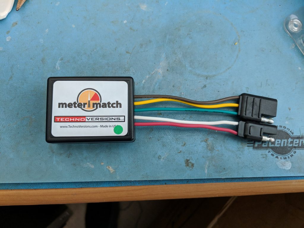
One very smart poster on the VMF by the name of Woodchuck suggested using an Arduino to map between the linear and non-linear values. It turns out that somebody has already done something similar. It’s from the company TechnoVersions and is called the Meter Match. I purchased one online and it arrived within a few days. Here is a picture of the Meter Match with some connectors I added as a part of my wiring project.

I wanted to build a wiring harness for the whole mess so that I could service the instrument cluster by simply unplugging the unit. I also needed to be able to reach the Meter Match so that I could calibrate the gauge without requiring access to the back of the instrument cluster. I chose to place the Meter Match in the console storage area. Another place for it could be in the glove compartment. I ordered some connectors and colored wires to build the harness.

I have a spare instrument cluster so I decided to test the gauge on my workbench with and without the Meter Match in an attempt to characterize the gauge’s behavior. This would permit me to test the Meter Match and perform an initial calibration before I installed everything in the car. Below are the results of my characterization. One thing to note is that the stock instrument cluster voltage regulator is about 5 volts. The meter match has a built in regulator that supplies the fuel gauge 8 volts. The fuel gauge behaves differently depending on whether it receives 8 volts or 5 volts. I characterized the gauge using both voltages with no Meter Match, and with 8 volts using the Meter Match.

Resistance (Ohms)No MM (5V)No MM (8V)MM (8V)
10FF+F+
153/4+F+F
253/8F3/4+
271/4+7/83/4
421/4-1/21/2-
501/83/81/4
60E+1/4-1/8
65E3/16E
75E1/8E
771/8E-
821/8

From this chart I can see that if the sending unit behaves in a linear fashion the MeterMatch should get my gauge fairly close even before I calibrate it in the car. The readings I got also match up fairly well with the posting on VMF for the original and replacement sending units. Now I need to get to work removing the instrument cluster and doing some wiring. I plan to power the MeterMatch from the accessory post of the ignition switch. I also plan to add a fuse in the +12V wire for safety. Since the tank is already fairly full fine tuning the calibration will take quite a bit of time and plenty of trial and error. My next post should be the final installation and testing. I will try to post again after the end of the 2019 car show season to talk about my calibration efforts.