I had been waiting for the weather to warm up a bit, and was finally rewarded with a nice day where I could devote a couple of hours to the A/C install. With most of the compressor and condenser work completed, it was time to turn my attention to the interior portion of the installation.
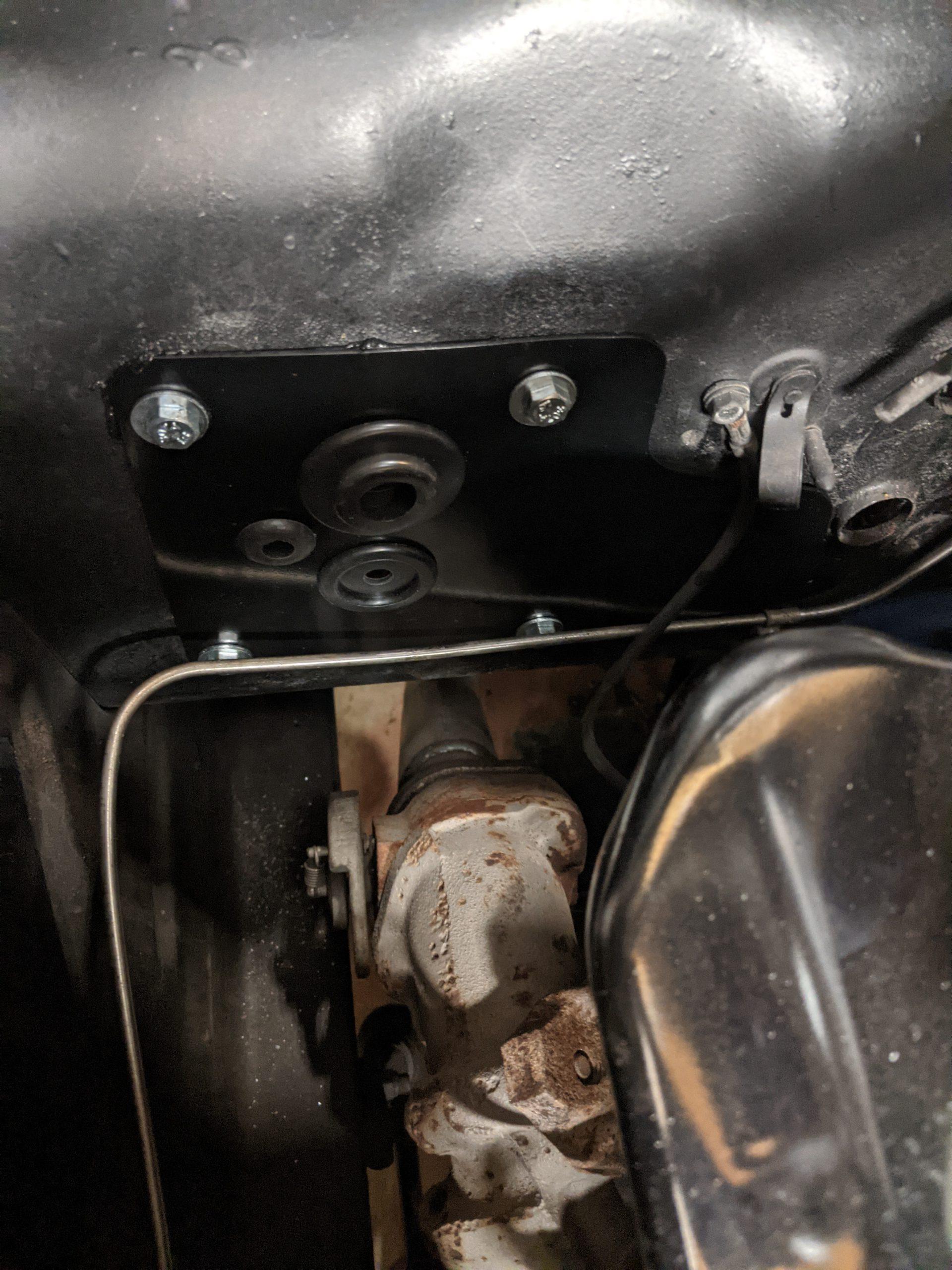
I started with installing the block off plate for the opening in the firewall where the original heater blower motor lived. I installed the supplied grommets in the block off plate, installed some sealer around the edge of the plate, and bolted it into place. It was held in with bolts that extend through the plate and the firewall into the interior. Locking nuts on the interior side securely bolt it in place. In order to start the nuts from the interior side without pushing the bolts back out into the engine compartment I put some painters tape over the bolt heads to hold them in place. Once I had all the bolts started I was able to tighten them down.
While I was working on the engine side of the firewall I decided to drill the two holes required for the evaporator studs to extend through the firewall. Locating where to drill them was easy since Vintage Air used the same locations that the factory used for installing A/C. The hole locations were marked with dimples for me to drill out. The hole closest to the right hand side of the firewall was easy to get to. For the hole closer to the center of the firewall I was unable to get a drill straight into the dimple as the engine blocked access to the dimple. I ended drilling a hole with a very small drill bit at a slight angle to mark where the dimple was. I then finished the hole from the interior of the car using the proper size drill bit.
The kit comes with new defroster vents that must be installed in place of the original vents. I had already removed the glove box and console to get the original heater core and box out of the car. I had hoped this would make the defroster vents easy enough to access. The passenger vent was no problem to remove. In order to more easily reach the driver’s side vent I chose to remove the instrument cluster. It is fairly easy to remove and made replacing the defroster vent much easier. The instructions don’t mention this step but I recommend doing it this way.
One thing I noticed about the new defroster vents is that they have no grill or screen to prevent objects that are placed on the dash from falling into the vents. The original vents have a grill to prevent this from happening, and I can say from personal experience that objects will eventually attempt to fall into the vent. I had some fiberglass screen material so I looked at using it to make a screen for the defroster vent. I didn’t like that it is very easy to rip and it would eventually wear out. I decided leave off the screen and proceeded to install the vents. I thought that I might try to install the screens on the hose end of the defroster vents. Later I had second thoughts and ordered some stainless steel grate material. I plan to remove the newly installed defroster vents, fit a grate to the opening, and reinstall the defroster vents. If it works out well I will post an update with some pictures of the finished product.
This is the metal grate material I ordered. The weather is expected to warm up in the next few days so I hope to be able to spend some time making a grate for the defroster vents. This was an unexpected slowdown in my progress, but I feel it is well worth the extra time.

Since the Vintage Air kit doesn’t use the passenger side fresh air vent it includes a block off plate to cover the hole in the cowl for the vent. I drilled three new holes to secure the block off plate, applied some sealer around the edges of the plate, and screwed it into place. I would have preferred that the A/C kit include a fresh air option, but none of the aftermarket kits I looked at included that option.
To finish up the afternoon’s work I measured and cut the new firewall insulation that came with my Quiet-Ride insulation kit. I need to go back and seal around the edges with some foil tape, but it looks like it fits fairly well. I still plan to add some insulation to the driver’s side firewall as well, but that doesn’t need to be completed before I install the rest of the A/C components.
Looks like cold weather for the next few days. Hopefully I will find some time and warm weather to continue the install next week.