I planned to include lots of pictures of this process, but with all the rain and the mess in my garage I decided to stick with mostly descriptive text. The only consolation is that there are many videos and descriptions of setting up and using the Quickjack. So I don’t feel terrible about having this entry consisting mainly of text.
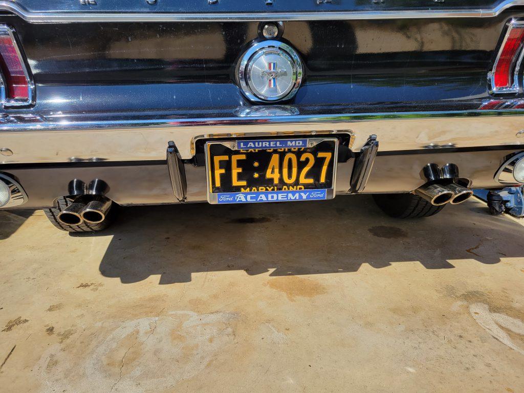
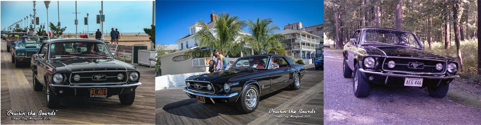
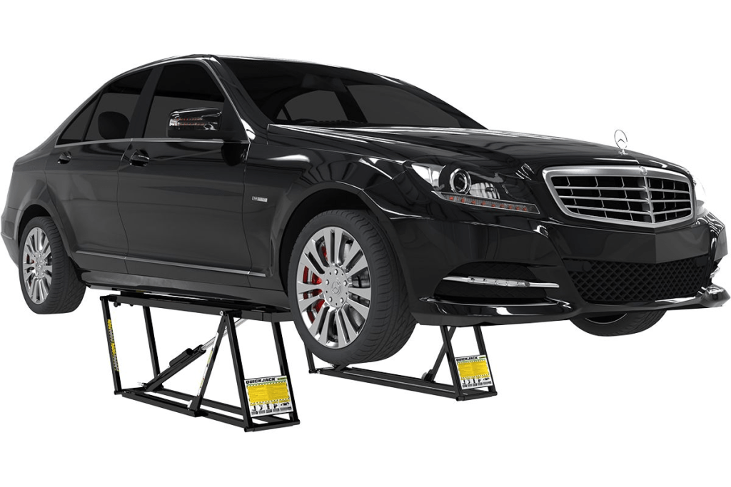
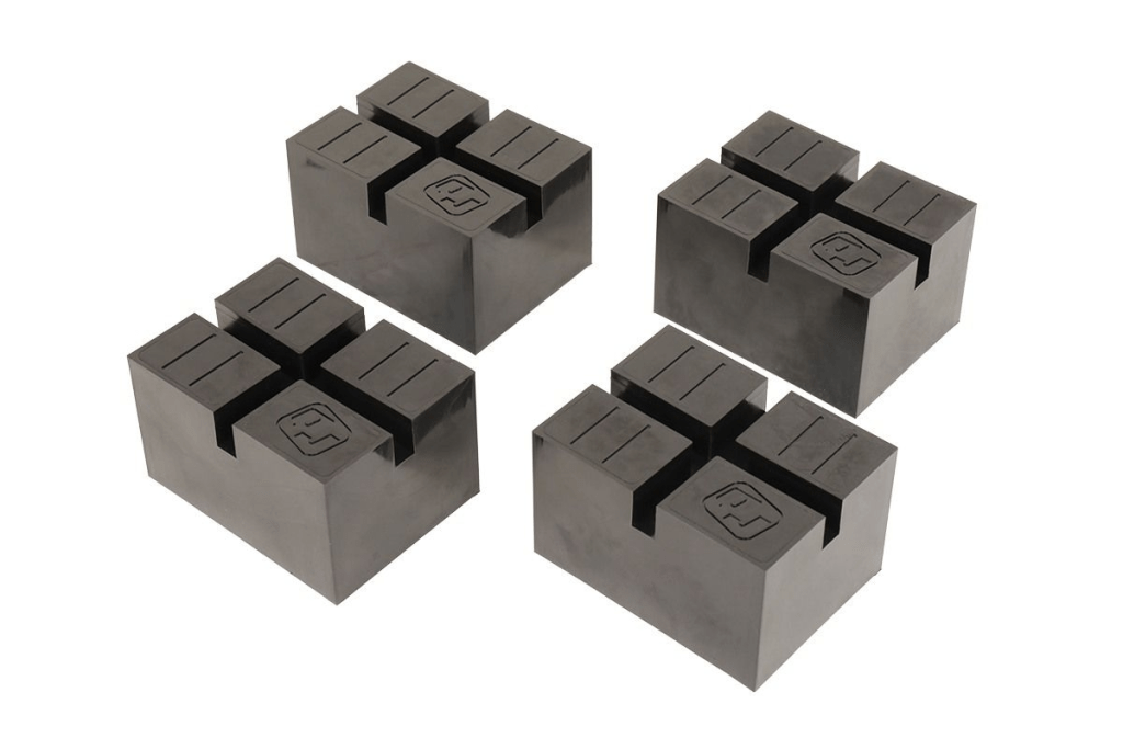
Costco was having a sale on a package deal of a Quickjack 5000TL along with a set of wall hangers and a set of pinch weld blocks. The combined price was $300 less than the normal price for just the Quickjack without the accessories. I had been wanting a Quickjack or some similar lifting device for quite a while but was unwilling to pay for one as they are expensive. The Quickjack 5000TL is rated for lifting up to 5000 pounds, so it has more than sufficient capacity to lift my Mustang. The lifting points on the mustang are along the pinch weld, so the pinch weld adapters are an accessory I would need to purchase regardless of whether I purchased a package deal or not. I decided that now is the time to purchase one. I know I will get plenty of use out of it.
The Quickjack requires some assembly before you can use it to lift a car. It was raining outside when I was ready to begin assembly, preventing me from spreading everything out in my driveway to work on. I chose to assemble the hoses inside where it is nice and dry. The thread sealant Quickjack provides requires 24 hours to set, so assembling them ahead of time would make them ready for the next sunny day. Then I would be able to complete the assembly and testing process outside in my driveway.
Assembling the hoses was very simple. I applied thread sealant to the fittings and screwed them together. I made the fittings tight, but not gorilla tight. I can test them for leaks once I complete final assembly and perform testing and bleeding of the unit. I also had a chance to install fittings on the power unit. Those fittings didn’t require any thread sealant, just some lubrication on the fitting O-rings. I also went to the auto parts store and purchased some ATF to use as hydraulic fluid in the pump. The Quickjack instructions specify that you can use any general-purpose ISO-32, ISO-46, or ISO-68 hydraulic oil or one of the following approved ATF fluids:
- Dexron III
- Dexron VI
- Mercon V
- Mercon LV
- Any synthetic multi-vehicle ATF
The next warm and dry day I prepared the frames. First, I installed right angle hydraulic hose fittings on the frames. This was as easy as removing a plug on the hydraulic cylinder, screwing the parts into the cylinder, and tightening the fittings with a wrench. After installing the fittings on both frames, I attached the short hoses I had previously assembled to the fittings I just finished installing. The last step in preparing the frames is to pressurize the pneumatic springs with 40-50 psi of air. Now everything was ready to set up the hydraulic system.
I connected the long hoses to the short hoses on the frames and to the power unit. Then I filled the power unit with hydraulic fluid. The instructions said to open the bleeder valves on each frame and run the power unit until fluid comes out of the bleeder. Once I saw bubble free fluid coming out of both bleeders, I closed the bleeders and lowered the jack.
After bleeding I checked all of the fittings for leaks. I did have to tighten up one of the fittings as it was leaking a bit. After that I observed no more leaks. At this point the Quickjack is ready for use. I do still plan to research casters that will make positioning the jack much easier. If I find a solution I like, I will document it in a future entry.
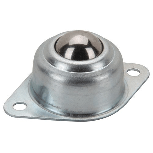
Update: I decided to experiment with some 1″ roller ball bearings I purchased at Harbor Freight. Since this is only an experiment, I attached the rollers using double sided 3M tape. I doubt the rollers will stay attached for long, but as a temporary trial it works just fine. The jacks are now so much easier to move around and position. Once the rollers do come off, I will find a more permanent way to attach them. There are plenty of videos online showing where to attach the rollers to the Quickjack in case anybody wants to duplicate what I have done.
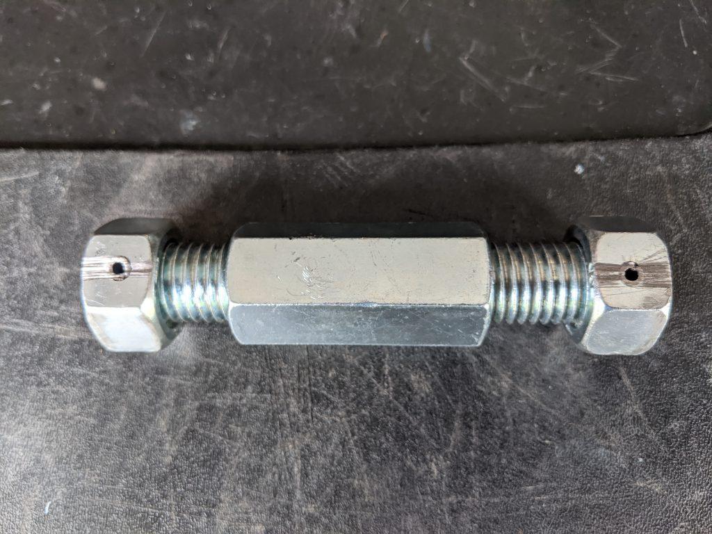
Here is a picture of the 1″ rollers I used. You will need 8 in all.