What I thought would be an easy buttoning up of the dash turned out to be more work than expected (just like everything else with this AC install). The first issue I ran into was that I couldn’t find the antenna connector on the back of the radio or the connector for the glove box light. I ended up removing the console once again to gain better access to the wiring. I eventually did manage to find the connectors and got them both hooked up. Believe it or not it took me about an hour to locate them both. Then I reinstalled the console, hopefully for the final time.
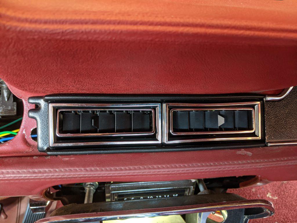
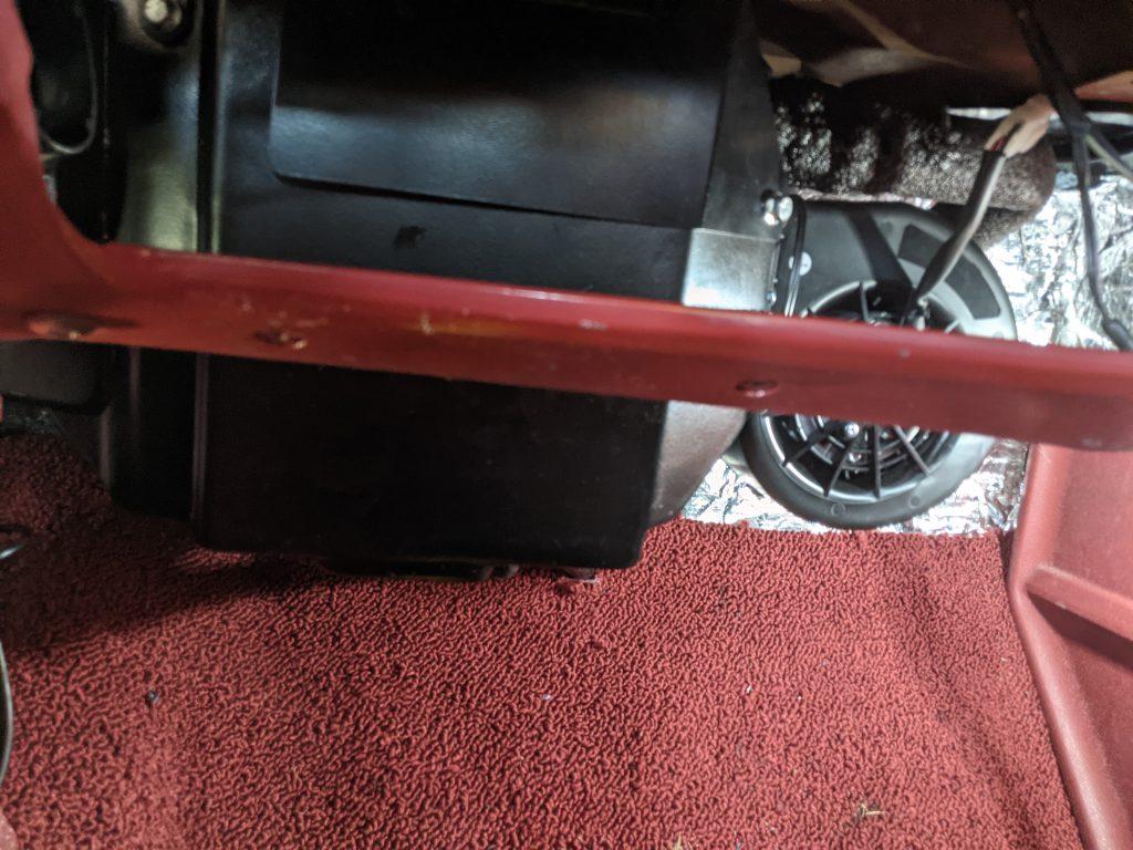
I returned to installing the ash tray and glove box. The duct hoses for the AC system managed to interfere with both the glove box and the ash tray liner. Moving the hoses around to make clearance caused them to interfere with the windshield wipers again. I spent some time repositioning hoses and everything is clear now, but opening and closing the glove box still rubs on one of the hoses a bit. I’ll revisit that sometime soon, but I just really needed to be able to button everything back up and drive the car some.
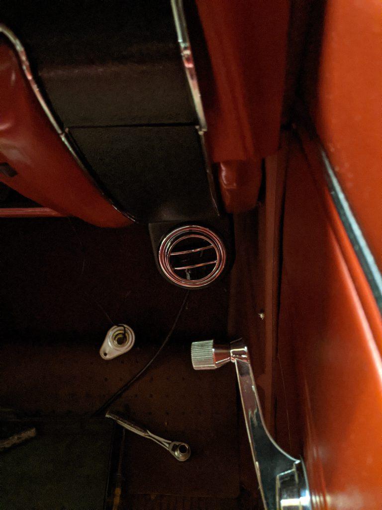
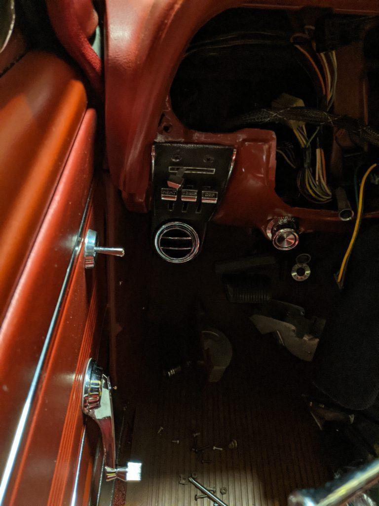
My previous mounting holes for the under dash lighting were now being used by the under dash AC vents. I found a suitable hole under the driver’s side dash and mounted the light there. On the passenger side I chose to use one of the glove box mounting screws. This worked, but the light bulb is exposed more than I like. I’m leaving it there for now, but I may have to either drill a new mounting hole or create a bracket that mounts the light in a less exposed location.
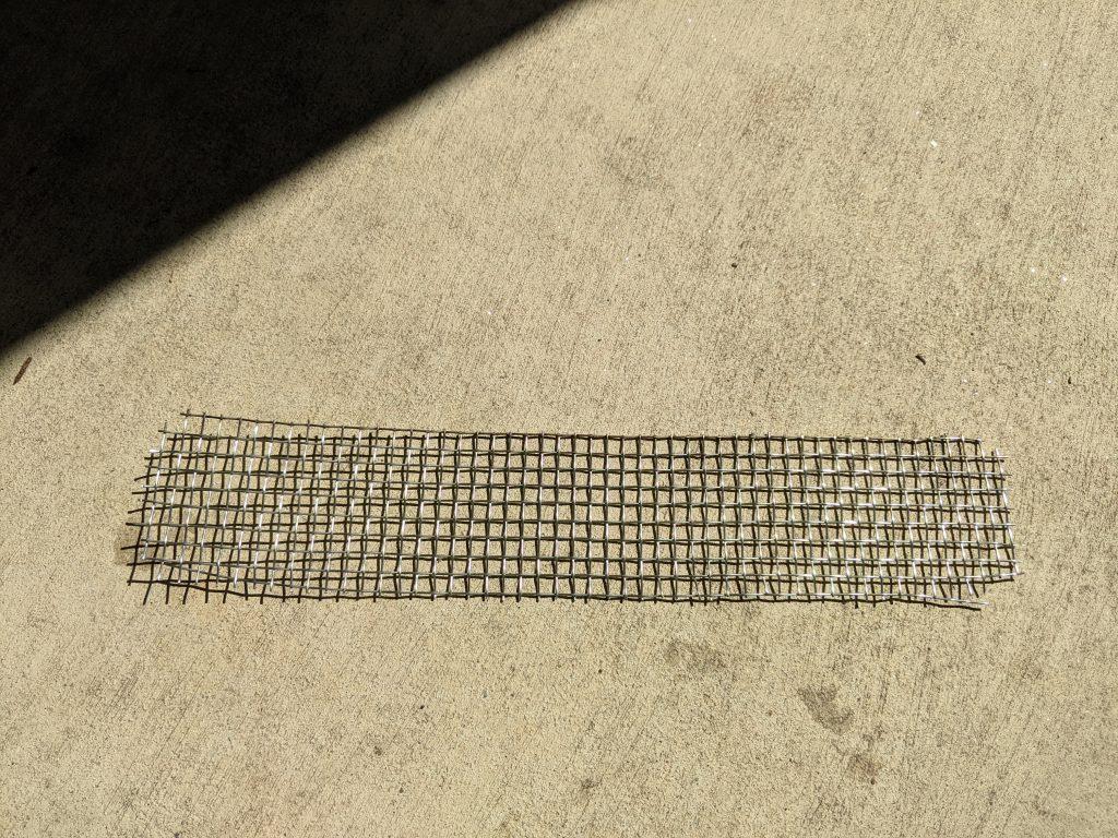
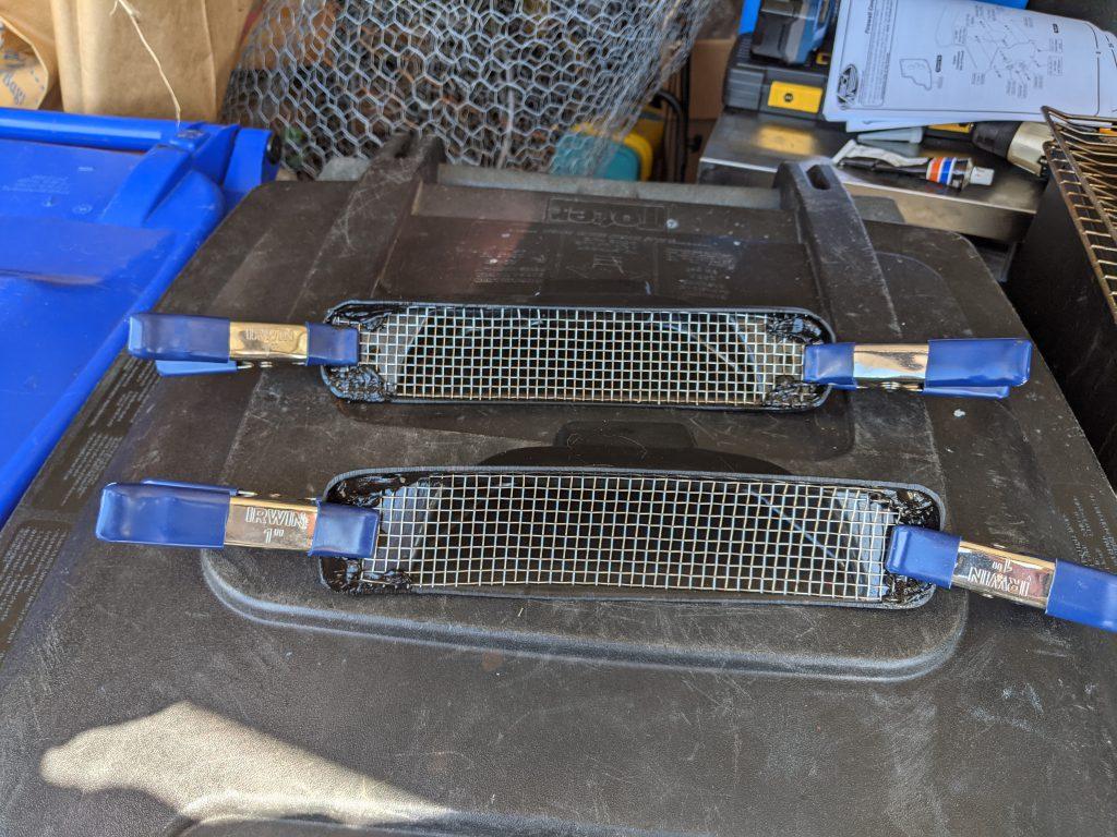
For now I’m declaring the job complete, even though I still have a few issues to iron out. This AC installation turned out to be more involved and time consuming than I expected based on just reading the instructions. The most difficult part for me was routing the “behind the dash” duct work. There isn’t much room back there to work with. The installation also turned out to be more expensive because I needed to purchase a bead lock crimping tool to make the hoses. That was unexpected as I thought the kit came with pre-made hoses rather than a make your own hose kit.
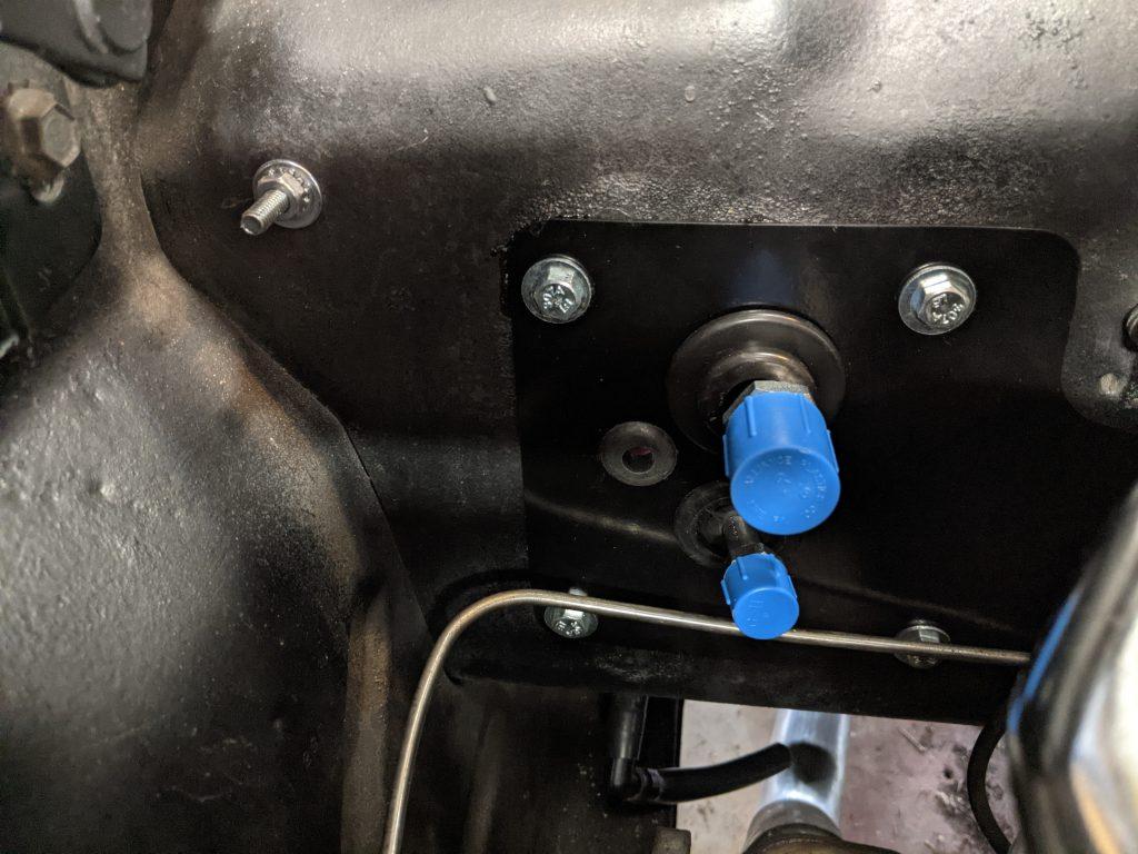
I’m now officially taking a break from working on the car for a while. I still have a few small (as in 1 hour or less) projects I might tackle. Since I have extra wiring loom I may clean up some non-AC related wiring in the engine compartment. I also purchased a Wagner adjustable PCV valve I can install and adjust. I had planned to rebuild the brake distribution block and residual pressure valve over the winter before I found the blown heater core. But if the brakes don’t give me any trouble I may save that for next winter.
I need to get the car cleaned up inside and outside so I can just enjoy driving it for a while. When the weather gets hotter outside I should now be able to stay nice and cool in the Mustang. If I feel comfortable with the pandemic situation I may even decide to attend some shows. I’m still undecided on large public gatherings at this point in time.